
Introduction: How to Identify the Input Device in PLC
Identify the input device in PLC by looking for the device that sends information or a signal to the PLC. In simple words, a PLC input device is any field device connected to a programmable logic controller that gives it information about what is happening in a machine, process, or automation system.
The easiest rule to remember is this: if the device gives information to the PLC, it is an input device. For example, a push button tells the PLC that an operator has pressed start or stop. A limit switch tells the PLC that a machine part has reached a certain position. A proximity sensor or photoelectric sensor tells the PLC that an object is present. Similarly, a pressure sensor, temperature sensor, level sensor, or encoder sends useful process information to the PLC.
Identifying input devices is important because it helps in PLC wiring, troubleshooting, automation learning, exams, and industrial maintenance. When you understand which device is sending the input signal, it becomes easier to read wiring diagrams, follow PLC programs, check input status lights, and find faults in an industrial control system.
What Is an Input Device in PLC?
A PLC input device is a device that collects information from a machine, process, operator, or environment and sends that information to the PLC input module. The PLC then reads this signal through its input terminals and uses it to decide what action should happen next.
For example, when an operator presses a start push button, the push button sends an input signal to the PLC. The PLC CPU reads that signal and may then turn on a motor through an output device such as a contactor, relay, or motor starter.
A simple way to understand it is:
Input device = sends signal to the PLC
Output device = receives command from the PLC
This difference is very important for beginners. A push button, limit switch, sensor, or transmitter is usually an input device because it provides information. A motor, solenoid valve, alarm, lamp, or heater is usually an output device because it performs an action after receiving a command from the PLC.
PLC input devices are commonly divided into two main types: digital input devices and analog input devices. A digital input gives only two conditions, such as ON/OFF, open/closed, or 1/0. An analog input gives a changing value, such as temperature, pressure, level, speed, or flow.
Quick Answer: Which Devices Are Input Devices in PLC?
The most common PLC input devices include push buttons, limit switches, proximity sensors, photoelectric sensors, selector switches, pressure switches, temperature sensors, pressure transmitters, level transmitters, and encoders. These devices are called input devices because they send information to the PLC about an operator command, machine condition, object position, or process value.
| PLC Input Device | What It Detects | Signal Type |
| Push button | Operator command | Digital |
| Limit switch | Machine position or end travel | Digital |
| Proximity sensor | Object presence without contact | Digital |
| Photoelectric sensor | Object detection using light | Digital |
| Selector switch | Manual mode selection | Digital |
| Pressure switch | Pressure limit reached | Digital |
| Temperature sensor | Temperature value | Analog |
| Pressure transmitter | Pressure value | Analog |
| Level transmitter | Tank level | Analog |
| Encoder | Speed or position pulses | Digital/Pulse |
A practical expert tip is to ask what question the device answers for the PLC. If a device answers questions like “Is the button pressed?”, “Is the object present?”, “What is the temperature?”, or “Where is the machine part?”, then it is most likely a PLC input device.
For example, a push button PLC input gives an operator command, a limit switch PLC input confirms position, a proximity sensor PLC input detects nearby objects, and an analog input device sends changing process values such as pressure, temperature, or level. This simple method makes it much easier to identify input devices in real machines, wiring diagrams, and PLC programs.
How to Identify the Input Device in a PLC System
To understand how to identify a PLC input device, you need to follow the signal path. In a PLC system, the input device is the part that sends information from the real world to the controller. This information may come from an operator, a machine part, a sensor, or a process condition.
A practical way to identify an input device is to use these five simple checks.
1. Check the Signal Direction
The first thing to check is the direction of the signal. If the signal goes from the field device to the PLC, the device is an input device.
For example, when a push button is pressed, it sends a signal to the PLC input terminal. When a sensor detects an object, it also sends a signal to the PLC. In both cases, the device is giving information to the controller, so it is an input device.
2. Check the PLC Terminal
Another helpful method is to look at the PLC terminal where the device is connected. If the wire goes to a terminal marked I, IN, DI, AI, X, input, or input channel, it is likely connected as an input.
Different PLC brands use different symbols. Some may use I0.0, some may use X0, and others may use addresses like I:0/0. Even though the labels are different, the purpose is the same: the terminal receives an input signal from a field device.
3. Check the Function of the Device
A device is usually an input device if it detects, senses, measures, or confirms a condition. This is one of the easiest ways for beginners to identify PLC inputs.
For example, a limit switch confirms that a machine part has reached a position. A photoelectric sensor detects an object on a conveyor. A temperature transmitter measures process temperature. These devices are not performing the final action; they are only giving information to the PLC.
4. Check the Device Type
Certain devices are commonly used as PLC inputs. Sensors, switches, push buttons, and transmitters are usually input devices because they send signals to the PLC.
Common examples include proximity sensors, selector switches, pressure switches, float switches, temperature transmitters, and level transmitters. These devices help the PLC understand what is happening in the machine or process.
5. Check the PLC Program
You can also identify an input device by checking the PLC program. In ladder logic, input devices often appear as contacts, such as normally open contacts, normally closed contacts, X0, I0.0, or I:0/0, depending on the PLC brand.
For example, a start push button may appear as a normally open contact in the ladder diagram. A stop button or safety contact may appear as a normally closed contact. These contacts represent real input devices connected to the PLC input module.
A useful practical tip is to never identify an input device only by its physical appearance. Always confirm it through the PLC wiring diagram, PLC input terminal, terminal number, and PLC address. In real industrial control panels, this habit helps avoid wiring mistakes and makes troubleshooting much easier.
Digital Input Devices in PLC
A digital input device in PLC sends a signal that has only two possible states. These states are commonly described as ON/OFF, 1/0, TRUE/FALSE, or open/closed. Because of this, digital inputs are also called discrete inputs or binary inputs.
For example, a push button is either pressed or not pressed. A limit switch is either activated or not activated. A proximity sensor either detects an object or does not detect it. These simple two-state signals are very common in PLC automation.
Common digital input devices include push buttons, selector switches, limit switches, proximity sensors, photoelectric sensors, pressure switches, float switches, emergency stop contacts, and door interlock switches. These devices are widely used because they give clear condition-based signals to the PLC.
In a conveyor system, a push button may be used to start or stop the conveyor. A photoelectric sensor may detect whether a product is present. A limit switch may confirm the end position of a moving part. A door interlock switch may tell the PLC whether a machine guard is closed. A float switch may detect high or low level in a tank.
Digital input devices are used in many practical applications, such as conveyor start/stop control, object detection, machine guard detection, cylinder position sensing, and tank high/low level detection. In most PLC tutorials and industrial training examples, push buttons, proximity sensors, and limit switches are frequently listed as the most common digital PLC input devices.
The main thing to remember is that a digital input gives the PLC a clear yes-or-no condition. It tells the PLC whether something has happened, whether something is present, or whether a condition is active.
Analog Input Devices in PLC
An analog input device in PLC sends a changing value to the controller instead of a simple ON/OFF signal. This means the PLC receives a range of values that represent a real-world measurement, such as temperature, pressure, level, flow, weight, humidity, or position.
For example, a digital input may only tell the PLC whether a tank is full or not full. An analog input, however, can tell the PLC the actual level of the tank, such as 25%, 50%, 75%, or 100%. This makes analog inputs very useful in process control and industrial measurement systems.
Common PLC analog signal ranges include 4–20 mA, 0–10 V, 1–5 V, thermocouple signals, and RTD signals. These signals are sent to an analog input module, which converts the real-world measurement into a value the PLC CPU can understand and use in the program.
Common analog input devices include temperature transmitters, pressure transmitters, level transmitters, flow transmitters, potentiometers, load cell transmitters, and humidity sensors. These devices are often used in industries such as water treatment, oil and gas, food processing, manufacturing, HVAC, and chemical plants.
A simple real-world example is a tank level transmitter. It may send 4 mA when the tank is empty and 20 mA when the tank is full. The PLC reads this current signal and converts it into a level value. If the signal is 12 mA, the PLC may understand that the tank is around half full, depending on how the scaling is set in the program.
Another example is a temperature transmitter connected to an RTD or thermocouple. The transmitter sends a changing signal to the PLC, and the PLC uses that value to control a heater, fan, valve, or alarm system.
The key difference is simple: a digital input device gives a two-state signal, while an analog input device gives a variable measurement. Both are important, but they are used for different purposes in PLC automation.
Common PLC Input Devices and Their Functions
A PLC input devices list usually includes switches, sensors, transmitters, and pulse-generating devices. Each device has a specific job, but all of them share one main purpose: they send information to the PLC so the controller can make the right decision.
Push Button
A push button input is one of the simplest and most common PLC input devices. It is used when an operator needs to give a manual command to the machine. Common push button functions include start, stop, reset, jog, emergency acknowledge, and manual operation.
Push buttons can be normally open or normally closed. A normally open push button completes the circuit when pressed, while a normally closed push button opens the circuit when pressed. In PLC panels, push buttons are often installed on the front of control panels, operator stations, and machine control boxes.
For example, when an operator presses a start button, the PLC receives the input signal and may then activate a motor, conveyor, or machine cycle through an output device.
Limit Switch
A limit switch detects physical movement or position. The main limit switch function is to confirm that a machine part has reached a certain point. It may detect travel end, door position, mechanical movement, or the position of a moving part.
Limit switches are common in conveyors, packaging machines, lifts, machine guards, and industrial doors. For example, a limit switch may tell the PLC that a cylinder has fully extended or that a guard door is closed.
Because limit switches usually require physical contact, they are often used where a machine part can safely touch the switch actuator. They are reliable, simple, and easy to understand in PLC troubleshooting.
Proximity Sensor
A proximity sensor detects object presence without physical contact. The main proximity sensor function is to sense whether an object is near the sensor and then send a signal to the PLC.
Two common types are inductive proximity sensors and capacitive proximity sensors. An inductive proximity sensor is mainly used for detecting metal objects. A capacitive proximity sensor can detect non-metal materials, liquids, powders, plastic, glass, and other materials depending on the application.
Proximity sensors are commonly used to detect the presence or absence of objects without touching them. This makes them useful in places where contact-based switches may wear out quickly. In PLC systems, they are often used on conveyors, counting stations, robotic fixtures, filling machines, and positioning systems.
Photoelectric Sensor
A photoelectric sensor PLC input uses light to detect objects. It sends a signal to the PLC when the light beam is blocked, reflected, or received, depending on the sensor type.
Photoelectric sensors are useful for detecting bottles, boxes, cartons, labels, bags, and moving products. They are widely used in conveyor systems, packaging lines, counting systems, and sorting machines.
For example, a photoelectric sensor on a conveyor can tell the PLC when a box reaches a certain position. The PLC can then stop the conveyor, start a filling process, activate a pusher, or count the product.
Pressure, Level, Temperature, and Flow Sensors
Pressure, level, temperature, and flow sensors are common industrial sensors used in process automation. These devices help the PLC monitor real-world process conditions.
Some of these devices work as digital switches. For example, a pressure switch may turn ON when pressure reaches a set limit. A float switch may turn ON when a tank reaches a high or low level.
Other devices work as analog transmitters. For example, a pressure transmitter may send a 4–20 mA signal to show the actual pressure value. A temperature transmitter may send a changing signal based on the measured temperature. A flow transmitter may send a signal based on how much liquid or gas is moving through a pipe.
These input devices are very important in systems such as water treatment plants, boilers, HVAC systems, chemical processes, pump stations, and manufacturing lines.
Encoder
An encoder PLC input sends pulses related to rotation, speed, direction, or position. It is commonly used where the PLC needs to track movement accurately.
Encoders are often connected to motors, conveyors, rollers, robotic systems, and positioning machines. For example, an encoder can help the PLC measure how far a conveyor has moved or how fast a motor shaft is rotating.
Some encoder signals are handled by normal digital inputs, but faster encoder signals often need a high-speed counter input module. This is because the PLC must count the pulses quickly and accurately.
Input Device vs Output Device in PLC
The difference between an input device and an output device is one of the most important PLC basics. Many beginners confuse the two, but the idea is simple.
An input device sends information to the PLC. An output device receives commands from the PLC. The input tells the PLC what is happening, and the output performs the action decided by the PLC program.
For example, a push button tells the PLC that an operator wants to start a machine. The PLC then sends a command to an output device such as a motor starter. In this case, the push button is the input device, and the motor starter is the output device.
| Input Device | Output Device |
| Push button | Motor starter |
| Limit switch | Solenoid valve |
| Proximity sensor | Indicator lamp |
| Temperature sensor | Heater |
| Pressure switch | Alarm horn |
| Encoder | VFD command output |
A simple memory trick is:
Input tells the PLC what is happening. Output performs the PLC’s decision.
For example, if a temperature sensor tells the PLC that the temperature is too low, the PLC may turn on a heater. If a pressure switch tells the PLC that pressure is too high, the PLC may activate an alarm horn. This is the basic idea behind automation input output control.
Understanding the PLC input and output difference also helps when reading wiring diagrams. Devices connected to input terminals are usually sensors and switches, while devices connected to output terminals are usually actuators, lamps, relays, valves, heaters, or motor control devices.
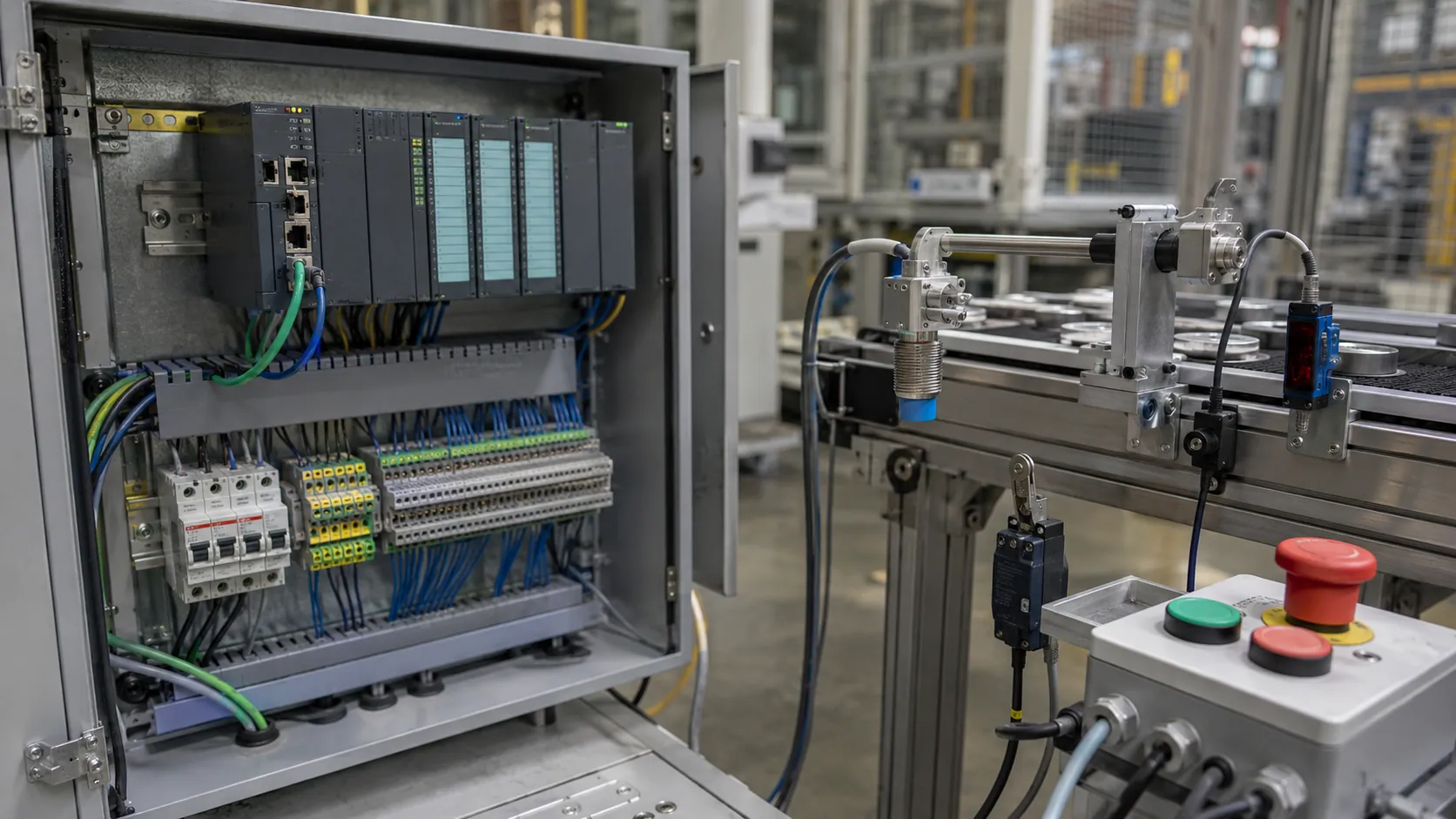
How PLC Input Devices Are Connected to the PLC
PLC input devices are connected to the controller through a PLC input module. The input module acts as the interface between the real-world field device and the PLC CPU. It receives the electrical signal from the device and allows the PLC to read it safely and correctly.
There are different types of input modules depending on the signal type. Common input module types include digital input modules, analog input modules, high-speed counter input modules, and RTD/thermocouple input modules.
A digital input module is used for ON/OFF devices such as push buttons, selector switches, limit switches, proximity sensors, and pressure switches. An analog input module is used for changing signals such as 4–20 mA or 0–10 V from transmitters. A high-speed counter input module is used for fast pulse signals from encoders. An RTD or thermocouple input module is used for temperature measurement.
In basic PLC input wiring, you may see 2-wire switches and 3-wire sensors. A 2-wire switch usually works like a simple contact that opens or closes a circuit. A 3-wire sensor usually has a power wire, a common or negative wire, and a signal wire that goes to the PLC input terminal.
Many industrial PLC systems use 24V DC input wiring. In these systems, technicians often need to understand PNP sensors, NPN sensors, sinking inputs, and sourcing inputs. A PNP sensor usually supplies positive voltage to the input when activated, while an NPN sensor usually switches the input toward the negative/common side. The exact wiring depends on the PLC input design and the sensor type.
The input common terminal is also important. It provides the reference point for the input circuit. If the common terminal is wired incorrectly, the PLC may not detect the input signal even if the field device is working.
A practical safety note is important here: always follow the PLC manual, wiring diagram, voltage rating, and plant safety rules before connecting any device. Never guess wiring only by wire color or device shape. In real industrial panels, correct field wiring protects the PLC, the machine, and the people working around it.
Real-World Examples of PLC Input Devices in Automation
Understanding PLC input device examples becomes easier when you see how these devices work in real machines. In an automation system, input devices help the PLC know what is happening before it makes a control decision. These examples show how different input devices are used in common industrial automation applications.
Example 1: Conveyor System
In a conveyor system, several input devices may work together to control product movement. A start push button tells the PLC that the operator wants to run the conveyor. Once the button is pressed, the PLC receives the input signal and may turn on the conveyor motor through an output device.
A photoelectric sensor can be installed beside the conveyor to detect a product, box, bottle, or carton. When the product passes in front of the sensor, the sensor sends a signal to the PLC. This conveyor PLC input may be used for counting products, stopping the conveyor, starting a filling process, or activating a sorting mechanism.
A limit switch may also be used to confirm the position of a moving part. For example, it can tell the PLC that a stopper, gate, or mechanical arm has reached its correct position. Without this input confirmation, the PLC may not safely move to the next step in the sequence.
Example 2: Water Tank System
A water tank system is another simple example of PLC input control. A float switch can detect high or low water level. When the water reaches a certain point, the float switch changes state and sends a digital input signal to the PLC.
A level transmitter provides more detailed information. Instead of only telling the PLC whether the tank is high or low, it sends a continuous tank level value. This type of tank level PLC input is usually analog and may use a signal such as 4–20 mA.
A pressure switch can also be used to protect the pump. If the pressure becomes too high or too low, the pressure switch sends a signal to the PLC. The PLC can then stop the pump, activate an alarm, or prevent damage to the system.
Example 3: Packaging Machine
In a packaging machine, input devices are used for detection, speed tracking, positioning, and safety. A proximity sensor may detect a metal part, machine component, or product holder. This helps the PLC confirm that the correct part is in place before the next step begins.
An encoder can track conveyor speed, roller rotation, or product position. The PLC reads encoder pulses to understand how far the machine has moved or how fast it is running. This is especially useful when the packaging process needs accurate timing.
An emergency stop contact also sends a safety input to the control system. However, it should not be treated like a normal push button. Emergency stop circuits often require proper safety relays or safety PLCs, depending on the machine design and safety requirements.
Example 4: HVAC or Process Plant
In an HVAC system or process plant, input devices often measure changing process values. A temperature sensor sends an analog value to the PLC so the system can control heating, cooling, or ventilation.
A pressure transmitter monitors process pressure in pipes, tanks, compressors, or air systems. The PLC can use this information to control pumps, valves, alarms, or shutdown logic.
A flow transmitter measures how much liquid, steam, air, or gas is moving through a pipe. In a process automation PLC system, this input helps maintain stable flow, protect equipment, and improve process control.
These examples show that PLC input devices are not limited to one type of machine. They are used in conveyors, tanks, packaging lines, HVAC units, pump stations, and many other industrial systems.
Common Mistakes When Identifying PLC Input Devices
Many beginners make mistakes when identifying PLC input devices because they focus only on the device shape instead of checking its function, wiring, and PLC connection. In real PLC input troubleshooting, this can lead to wrong assumptions and wasted time.
One common mistake is calling a motor an input device. A motor is usually an output device because it receives a command from the PLC through a contactor, starter, relay, or drive. The motor may have feedback sensors connected to the PLC, but the motor itself is not normally the input device.
Another mistake is confusing sensor power wires with signal wires. A 3-wire sensor usually has a supply wire, a common wire, and a signal wire. Only the signal wire usually goes to the PLC input terminal. If you do not identify the signal wire correctly, you may misread the wiring diagram or connect the device incorrectly.
Some learners also assume that every sensor is analog, but this is not true. Many sensors are digital. A proximity sensor, photoelectric sensor, pressure switch, and float switch often send simple ON/OFF signals. Analog sensors and transmitters send changing values, such as pressure, temperature, level, or flow.
Ignoring the NO/NC contact type is another common error. A normally open contact and a normally closed contact behave differently in a PLC circuit. For example, a stop button or safety contact may be wired as normally closed so the PLC can detect a broken wire or open circuit condition.
Mixing up PNP and NPN wiring can also cause input problems. A PNP sensor and an NPN sensor switch the signal differently, and the PLC input module must match the correct sinking or sourcing input style. This type of PNP NPN confusion is a common cause of a PLC input not turning ON.
Another important mistake is confusing the input module vs input device. The input device is the field device, such as a sensor or switch. The input module is the PLC hardware that receives the signal. Both are part of the input system, but they are not the same thing.
Beginners may also forget to check PLC address labels. A wire may be connected to a terminal, but you still need to know the input address, such as I0.0, X0, or I:0/0, to find it in the PLC program. Without checking the input address, it becomes difficult to connect the physical device to the ladder logic.
Another uncommon but important point is that some devices can provide both digital and analog signals. For example, some pressure devices may include a switch output and an analog transmitter output. This means you should not identify a device only by its name. You should check the datasheet, wiring, and terminal labels.
Finally, an emergency stop should not be treated as a normal push button. Although it may send an input signal, emergency stop circuits often involve safety-rated components. Always consider machine safety rules, plant standards, and the control system design before working with safety inputs.
In real troubleshooting, the best approach is to identify the device by checking its function, wiring, terminal label, PLC address, and live PLC input LED. This reduces the chance of a wiring error and helps you find the problem faster.
Expert Checklist to Identify Any PLC Input Device
Use this simple PLC input checklist whenever you need to identify an input signal in a real panel, wiring diagram, or PLC program.
- Does the device sense or detect something?
- Does it send a signal to the PLC?
- Is it connected to a PLC input module?
- Is the terminal marked I, IN, DI, AI, X, or input?
- Does the PLC program use it as a contact or input tag?
- Is the signal digital, analog, or pulse?
- Does the PLC input status LED change when the device is activated?
- Does the wiring match the sensor type, voltage rating, PNP/NPN style, and input common terminal?
A practical field tip is this: “When checking a machine panel, I first look at the PLC input LED while activating the device. If the LED changes, it usually confirms that the device is feeding an input signal to the PLC. After that, I verify the wiring diagram and PLC address.”
This method works well because it combines physical checking with electrical and program confirmation. Instead of guessing, you confirm the field device troubleshooting path step by step: device function, wire connection, terminal number, input address, and PLC tag. Once all of these match, you can confidently say that the device is a PLC input device.
Conclusion: Identify the Input Device in PLC the Easy Way
To identify the input device in PLC, look for the device that sends information to the PLC. A PLC input device does not perform the final action. Instead, it detects, senses, measures, or confirms a condition so the PLC can make the right control decision.
Common PLC input devices include push buttons, limit switches, proximity sensors, photoelectric sensors, pressure sensors, temperature sensors, level sensors, and encoders. Some of these devices send simple digital input signals, such as ON/OFF or TRUE/FALSE. Others send analog input values, such as temperature, pressure, level, flow, or speed.
The best way to confirm an input device is to check its function, wiring, PLC terminal, input module, and PLC program address. In real automation troubleshooting, you should also look at the PLC input status LED and compare it with the wiring diagram.
Once you understand that an input device “talks to the PLC,” identifying PLC inputs becomes much easier in exams, wiring diagrams, training labs, and real industrial panels.
FAQs About Identifying PLC Input Devices
What is an input device in PLC?
An input device in PLC is a field device that sends information or signals to the PLC. Common examples include a push button, sensor, switch, transmitter, limit switch, proximity sensor, and photoelectric sensor. The PLC reads this input signal and then makes a control decision based on the program.
Is a sensor an input device in PLC?
Yes, most sensors are PLC input devices because they detect real-world conditions and send signals to the PLC. For example, a proximity sensor detects object presence, a temperature sensor measures temperature, and a level sensor checks liquid level. These signals help the PLC understand what is happening in the machine or process.
Is a motor an input device in PLC?
No, a motor is usually an output device, not an input device. A motor receives a command from the PLC through a starter, relay, contactor, or drive. However, sensors connected to the motor, such as an encoder or overload feedback contact, may work as PLC input devices.
Is a push button an input or output device?
A push button is an input device because it sends an operator command to the PLC. For example, when an operator presses a start button, the PLC receives the signal and may turn on a motor, conveyor, pump, or other output device.
What are the two main types of PLC inputs?
The two main types of PLC inputs are digital/discrete inputs and analog inputs. A digital input gives an ON/OFF signal, such as a push button or limit switch. An analog input gives a changing value, such as temperature, pressure, level, or flow.
How do I know if a device is connected as a PLC input?
You can identify a PLC input by checking whether the device is wired to a PLC input terminal, shown as an input address in the PLC program, and changes the PLC input status LED when activated. It is also helpful to confirm the device function, wiring diagram, terminal label, and PLC address.
Disclaimer
This article is for general informational purposes only and is meant to help readers understand PLC input devices in a simple way. Practical results, wiring methods, device behavior, and troubleshooting steps may vary based on the PLC brand, system design, safety standards, and application. Always refer to the official PLC manual, wiring diagram, and qualified technical guidance when working with real industrial equipment.